RILT Specifications and Information:
|
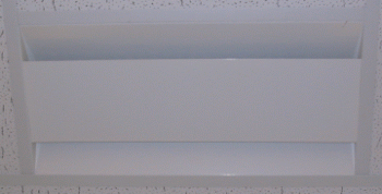
The RILT is a high induction linear diffuser designed for low temperature applications.
- Factory sealed, integral plenum with internally lined insulation protects against condensation.
- Discharge angle of leaving air designed to maintain a tight horizontal pattern even with varying air volumes.
- Face of diffuser is flush with the ceiling tiles providing a smooth appearance to blend into ceiling system.
- Diffuser available in two and four foot lengths.
- The RILT diffusers have a one way or two way blow pattern that is optional based on the application.
|

|
- - - Top Of Page - - - |
RILT Air Discharge Pattern (Throw):
|

|
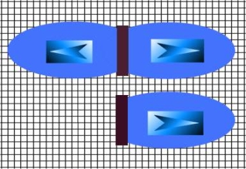
The RILT series of low temperature diffusers are available with one-way or two-way opposite high induction jets.
Thermal Core has been tested and engineered to maximize the performance in constant velocity as well as in VAV applications.
|
- - - Top Of Page - - - |
RILT Sizes and Linear Throw Capacity:
|
| Available Inlet Sizes |
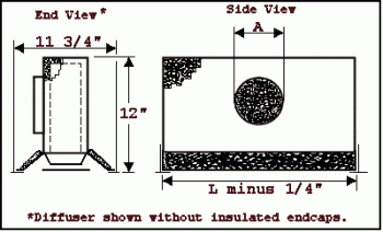
| Available Lengths (L) | 6" rnd | 8" oval | 10" oval |
| 24" | * | * | * |
| 48" | * | * | * |
| Inlet Widths (A) | 6-1/4" | 9-3/8" | 12" |
|

|
- - - Top Of Page - - - |
General Specifications for the Thermal Core RILT Diffusers:
|
- General: Air diffusers shall be of the sizes shown on the drawings. Units shall have factory catalog performance ratings, which conform to CFM, temperature and velocity profiles, static pressure drop, and generated noise criteria designated. The diffusers shall be a high induction type, specifically designed for air distribution at temperatures down to 35 degrees Fahrenheit, without dumping or forming condensation on the diffuser’s surfaces and provide Air Distribution Performance Index (ADPI*) above 95 at primary supply air volumes down to .10 CFM/ft.
- Construction: The Diffusers shall be constructed of a fire retardant material and shall be able to pass the UL 25/50 Flame and Smoke Spread Tests. Plenums shall be factory constructed with inlet collars sized as scheduled. Internal surfaces shall be thermally and acoustically insulated with glass fiber material. The plenum shall be completely sealed to provide a vapor barrier and avoid air leakage. Plenums shall be insulated to provide an overall R 4.5 value at 40 degrees Fahrenheit.
- Ceiling Compatibility: Provide diffusers with border styles that are specifically manufactured to fit into ceiling module with accurate fit and adequate support. Refer to general construction drawings and specifications for types of ceiling systems which will contain each type of ceiling air diffuser.
- Performance Rating: Performance of the Air diffusers shall be based on independent laboratory tests of factory built plenum/diffuser assemblies run in accordance with ADC** Standard 1062R4.
The diffusers shall be capable of supplying 35 degree Fahrenheit air directly into a room without any tendency for the supply air envelope to drop, "dump", or fall into the room. This shall be accomplished throughout its entire operating range from complete shutoff to one hundred percent flow.
The diffusers shall be capable of providing and ADPI of 95 or above in any room, when selected and located in accordance with the standard Thermal Core procedure. The diffusers shall be capable of providing secondary room air motion and temperature profile from the floor to the seven foot high level evenly maintained at any point in the conditioned area, and confirmed in an ADC certified, independent laboratory test room. See Test Data.
- The diffusers shall be capable of supplying 35-degree Fahrenheit air directly into a room without condensation forming on its surfaces.
- Types: Provide ceiling diffusers of type, capacity, performance, and with accessories and finishes as listed on Air Distribution Schedule.
Requests for substitution of the specified diffusers shall be accompanied by independent ADC certified laboratory test data, documenting the performance in this specification will be complied with. Calculations, either computerized or manual, shall be submitted fore each conditioned room assuring that the minimum ADPI listed in the schedule will be achieved by the substitute.diffusers.
*Air Diffusion Council
**"ADPI" as described in the 1989 ASHRAE Fundamentals Handbook, Chapter 31
|
- - - Top Of Page - - -
|
RILT - Standard and High Capacity Performance Charts:
|
| RILT High Capacity: 48" 2-Way Blow |
Air Flow CFM |
Static Pressure Inch WC |
Total Pressure Inch WC |
Throw1 |
Induction2 Ratio
@ 150 FPM1 |
NC3 |
AK4 |
Inlet Size |
| 100 | .01 | .03 | 4, 7, 10 | 6:1 | <20 | .2231 | 6" RND |
| 150 | .03 | .04 | 5, 8, 11 | 8:1 | <20 | .2231 | 8" OVL |
| 200 | .03 | .05 | 7, 10, 13 | 11:1 | <20 | .2231 | 8" OVL |
| 250 | .06 | .09 | 9, 12, 16 | 14:1 | <20 | .2231 | 8" OVL |
| 300 | .08 | .10 | 10, 14, 16 | 17:1 | <20 | .2231 | 10" OVL |
| 350 | .11 | .14 | 12, 15, 20 | 20:1 | <20 | .2231 | 10" OVL |
| 400 | .14 | .17 | 13, 16, 21 | 23:1 | 21 | .2231 | 10" OVL |
|
| RILT High Capacity: 48" 1-Way Blow |
Air Flow CFM |
Static Pressure Inch WC |
Total Pressure Inch WC |
Throw1 |
Induction2 Ratio
@ 150 FPM1 |
NC3 |
AK4 |
Inlet Size |
| 50 | .01 | .03 | 4, 7, 10 | 6:1 | <20 | .1116 | 6" RND |
| 100 | .03 | .05 | 7, 10, 13 | 11:1 | <20 | .1116 | 6" RND |
| 150 | .08 | .10 | 10, 14, 16 | 17:1 | <20 | .1116 | 8" OVL |
| 200 | .14 | .17 | 13, 16, 21 | 23:1 | 21 | .1116 | 8" OVL |
| 250 | .23 | .26 | 15, 17, 26 | 28:1 | 28 | .1116 | 10" OVL |
| 300 | .31 | .35 | 17, 19, 30 | 34:1 | 33 | .1116 | 10" OVL |
| 325 | .37 | .41 | 18, 20, 32 | 37:1 | 35 | .1116 | 10" OVL |
|
| RILT High Capacity: 24" 2-Way Blow |
Air Flow CFM |
Static Pressure Inch WC |
Total Pressure Inch WC |
Throw1 |
Induction2 Ratio
@ 150 FPM1 |
NC3 |
AK4 |
Inlet Size |
| 50 | .01 | .01 | 5, 8, 11 | 6:1 | <20 | .105 | 6" RND |
| 75 | .03 | .04 | 7, 10, 13 | 9:1 | <20 | .105 | 6" RND |
| 100 | .04 | .06 | 9, 12, 16 | 12:1 | <20 | .105 | 6" RND |
| 125 | .07 | .10 | 10, 14, 16 | 15:1 | <20 | .105 | 6" RND |
| 150 | .10 | .11 | 12, 15, 20 | 18:1 | <20 | .105 | 8" OVL |
| 175 | .14 | .16 | 13, 16, 21 | 21:1 | 21 | .105 | 8" OVL |
| 200 | .18 | .20 | 14, 16, 23 | 24:1 | 23 | .105 | 8" OVL |
| 225 | .22 | .25 | 15, 17, 26 | 28:1 | 28 | .105 | 8" OVL |
| 250 | .29 | .32 | 16, 18, 27 | 30:1 | 32 | .105 | 8" OVL |
| 275 | .34 | .36 | 17, 19, 30 | 33:1 | 33 | .105 | 10" OVL |
| 300 | .40 | .42 | 18, 20, 32 | 36:1 | 35 | .105 | 10" OVL |
|
| RILT High Capacity: 24" 1-Way Blow |
Air Flow CFM |
Static Pressure Inch WC |
Total Pressure Inch WC |
Throw1 |
Induction2 Ratio
@ 150 FPM1 |
NC3 |
AK4 |
Inlet Size |
| 25 | .01 | .01 | 5,8,11 | 6:1 | <20 | .0525 | 6" RND |
| 50 | .04 | .04 | 9,12,16 | 12:1 | <20 | .0525 | 6" RND |
| 75 | .10 | .11 | 12,15,20 | 18:1 | <20 | .0525 | 6" RND |
| 100 | .18 | .20 | 14,16,23 | 24:1 | 23 | .0525 | 6" RND |
| 125 | .29 | .32 | 16,18,27 | 30:1 | 32 | .0525 | 6" RND |
| 150 | .40 | .41 | 18,20,32 | 36:1 | 35 | .0525 | 6" RND |
|
| RILT Standard Capacity 24" 1-Way Blow |
Air Flow CFM |
Static Pressure Inch WC |
Total Pressure Inch WC |
Throw1 |
Induction2 Ratio
@ 150 FPM1 |
NC3 |
AK4 |
Inlet Size |
| 50 | .07 | .07 | 9,12,17 | 16:1 | <20 | .041 | 6" RND |
| 75 | .17 | .18 | 12,14,21 | 24:1 | 25 | .041 | 6" RND |
| 100 | .30 | .32 | 14,17,23 | 33:1 | 33 | .041 | 6" RND |
| 115 | .43 | .43 | 15,18,24 | 37:1 | 35 | .041 | 6" RND |
|
| RILT Standard Capacity 24" 2-Way Blow |
Air Flow CFM |
Static Pressure Inch WC |
Total Pressure Inch WC |
Throw1 |
Induction2 Ratio
@ 150 FPM1 |
NC3 |
AK4 |
Inlet Size |
| 50 | .01 | .01 | 6,9,12 | 8:1 | <20 | .082 | 6" RND |
| 75 | .04 | .04 | 8,11,14 | 12:1 | <20 | .082 | 6" RND |
| 100 | .07 | .09 | 9,12,17 | 16:1 | <20 | .082 | 6" RND |
| 125 | .12 | .15 | 11,13,20 | 20:1 | <20 | .082 | 6" RND |
| 150 | .17 | .18 | 12,14,21 | 24:1 | 25 | .082 | 8" OVL |
| 175 | .24 | .26 | 13,16,22 | 28:1 | 29 | .082 | 8"OVL |
| 200 | .30 | .32 | 14,17,23 | 33:1 | 33 | .082 | 8" OVL |
| 225 | .39 | .41 | 15,18,24 | 37:1 | 35 | .082 | 8" OVL |
|
| RILT Standard Capacity 48" 1-Way Blow |
Air Flow CFM |
Static Pressure Inch WC |
Total Pressure Inch WC |
Throw1 |
Induction2 Ratio
@ 150 FPM1 |
NC3 |
AK4 |
Inlet Size |
| 50 | .01 | .01 | 6,9,12 | 8:1 | <20 | .082 | 6" RND |
| 100 | .07 | .09 | 9,12,17 | 16:1 | <20 | .082 | 6" RND |
| 150 | .17 | .18 | 12,14,21 | 24:1 | 25 | .082 | 8" OVL |
| 200 | .30 | .32 | 14,17,23 | 33:1 | 33 | .082 | 8" OVL |
| 230 | .41 | .44 | 15,18,24 | 37:1 | 35 | .082 | 8" OVL |
|
| RILT Standard Capacity 48" 2-Way Blow |
Air Flow CFM |
Static Pressure Inch WC |
Total Pressure Inch WC |
Throw1 |
Induction2 Ratio
@ 150 FPM1 |
NC3 |
AK4 |
Inlet Size |
| 100 | .01 | .01 | 6,9,12 | 8:1 | <20 | .164 | 6" RND |
| 150 | .04 | .05 | 8,11,14 | 12:1 | <20 | .164 | 6" RND |
| 200 | .07 | .09 | 9,12,17 | 16:1 | <20 | .164 | 6" RND |
| 250 | .12 | .15 | 11,13,20 | 20:1 | <20 | .164 | 6" RND |
| 300 | .17 | .19 | 12,14,21 | 24:1 | 25 | .164 | 8" OVL |
| 350 | .24 | .27 | 13,16,22 | 28:1 | 29 | .164 | 8" OVL |
| 400 | .30 | .33 | 14,17,23 | 33:1 | 33 | .164 | 8" OVL |
| 450 | .39 | .43 | 15,18,24 | 37:1 | 35 | .164 | 8" OVL |
|
Notes:
- Throw data is given as the distance in feet to terminal velocities of 150, 100, and 50 FPM
- Induction ratio is the ratio of primary air to total air movement at 150 FPM
- NC criteria represents the noise criteria which will not be exceeded by the soundpressure in any of the octave bands, 2nd through 7th, with room absorption of 10 DB.
- AK represents the effective mean area of each diffuser.
|
- - - Top Of Page - - -
|
RILT Test Data:
|
| Test Parameters (Gen. Specs. D & E) |
| Test Room Dimensions | 20'W x 24' L x 9' H |
| Test Room Area | 480 sq. ft. |
| Test Room Volume | 4320 cu ft. |
| Supply Air Temperature | 40 degree Fahrenheit |
|
| Supply Air Volume 1 (D) | 135 CFM |
| CFM/ft | .28 | | Minimum Uniform Room Secondary Air Motion | 25 FPM |
| Air Distribution Performance Index | 100 |
| Temperature Profile Variance | +/- 1.5 degrees F |
|
| Supply Air Volume 2 (D) | 60 CFM |
| CFM/ft | .12 | | Minimum Uniform Room Secondary Air Motion | 18 FPM |
| Air Distribution Performance Index | 93 | | Temperature Profile Variance | +/- 1.5 degrees F |
|
| Condensation (E) |
| Test Room as Described Above | Air Performance Test | Condensation Test |
| Supply Air Temperature | 40 deg. F | 35 deg. F |
| Room Air Temperature | 75 deg. F | 85 deg. F |
| Room Relative Humidity | 40% | 85% |
|
- - - Top Of Page - - -
|